3D Printing: OpenSCAD
5 June 2013
This resource works through some common techniques using the 3D modelling application OpenSCAD to create a simple model suitable for 3D printing.
Resources
OpenSCAD: http://www.openscad.org/
Files: Castle Files (.zip)
License: Creative Commons
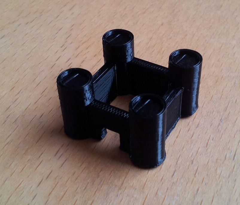
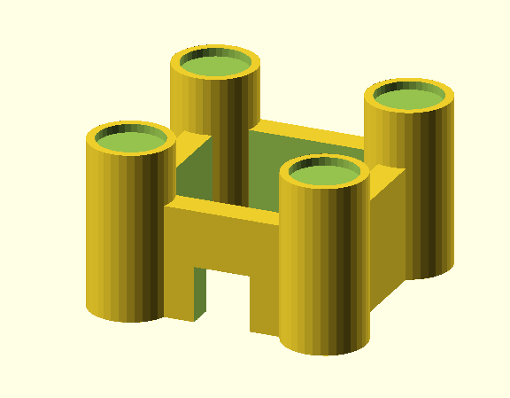
We are going to create this simple castle with four main walls, four towers and a door.
The dimensions used throughout this tutorial are very small (less that 1cm in most cases) so the resulting model is small. Feel free to increase the values or scale up before 3D printing.
OpenSCAD: The Basics
OpenSCAD is a 3D modelling tool that is ideal for creating objects for 3D printing.
Instead of interacting directly with the 3D model you write script that OpenSCAD uses to create objects. It can be a little tricky to get used to but it allows for accuracy and creates solid objects both of which are very important in 3D printing.
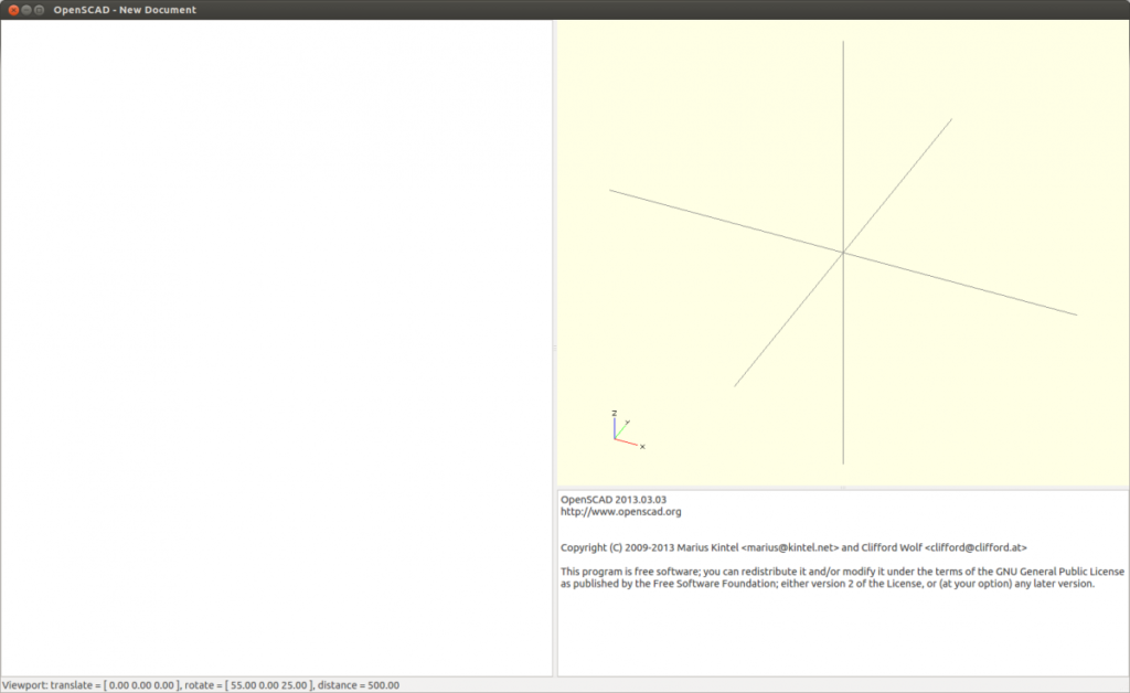
OpenSCAD has a very simple interface that includes an area for writing script (on the left), an area where the rendered 3D object will appear (on the right), and an area for progress, errors and general notifications while rendering an object.
Basic Controls
Most of the work in OpenSCAD is writing the script so there is less need to move the object itself around but it does have ways of rotating and moving the entire model to see obscured parts.
Mouse
For a standard mouse device with a central scroll wheel
Left mouse button: rotates the entire scene
Right mouse button: moves the entire scene
Middle scroll wheel: zooms in and out
Alternate Device Controls:
For devices like a drawing tablet
Ctrl + Left button: rotates the entire scene
Ctrl + Right button: moves the entire scene
Ctrl + Shift + Left button: zooms in and out
Viewport shortcuts
There are a number of standard views of the object that can be used by using the following shortcut keys or from the View menu at the top of the screen.
Ctrl + 4: Top
Ctrl + 5: Bottom
Ctrl + 6: Left
Ctrl + 7: Right
Ctrl + 8: Front
Ctrl + 9: Back
Modelling the main walls
The first step is to create the walls. We could set up for individual walls but in this case we are going to make them out of a single cube.
Add the following to the script area:
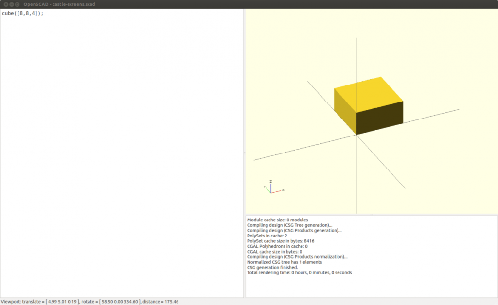
cube([8,8,4]);
Notes:
cube: tells OpenSCAD to render a cube.
([8,8,4]): dimensions for the sides in the X, Y and Z directions respectively. In this case X and Y are horizontal axes, Z is vertical. If a single number was used here, e.g. cube(6); all of the sides would be the same length. Our cube will be 8 units in the X and Y direction and 4 units high.
OpenSCAD uses generic units for dimensions but in our model they will become millimeters so you can think of the cube as being 8mm x 8mm x 4mm.
Compile the cube
Compile the cube by selecting the Design menu at the top of the screen and selecting Compile. A cube shape should appear in the object area.
We are now going to use a second cube to cut a hole in the middle of this one.
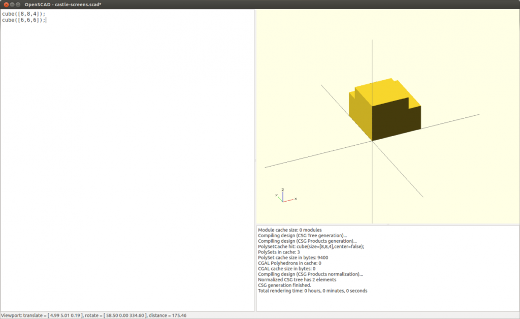
Add the following line so your script looks like this:
cube([8,8,4]);
cube([6,6,6]);
Compile (F5) and you should see a new cube.
This cube is not centered on the first one so the next step is to translate it so that it is. Translate really just means we are going to move the cube.
Add a translate just before the second cube line:
cube([8,8,4]);
translate([1,1,-1]) cube([6,6,6]);
Notes:
translate: this tells OpenSCAD to translate whatever follows, the cube in this case.
([1,1,-1]): move the object 1 unit in the X direction, 1 unit in the Y direction, and -1 in the Z direction (i.e. down)
Take care with the different brackets.
Compile (F5) and you should see the new cube has moved to the center of the larger cube. It also hangs down below slightly.
Make a hole
Now that the second cube is in the correct place we are going to make it cut a hole through the first cube. This is known as a difference function and is actually pretty common in graphics tools along with union, intersection, exclusion.
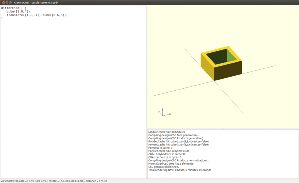
We are going to wrap our current script in a difference function like this:
difference() {
cube([8,8,4]);
translate([1,1,-1]) cube([6,6,6]);
}
Notes:
difference(): takes the second (and any following) objects and removes them from the first object.
Don’t forget the closing curly bracket.
Compile this (F5) and the second cube should now be a hole in the first. These are our castle walls.
Modelling the Towers
There are four towers in each corner of the castle and each is made up a cylinder with a small hole at the top. We are going to start by modelling a single tower.
Add the following to the bottom of your script:
cylinder(6,1.5,1.5, $fn=35);
Notes:
cylinder: this tells OpenSCAD to render a cylinder
6: this is the height of the cylinder
1.5: this is the radius of one end
1.5: this is the radius of the other end
$fn=35: this smooths the cylinder by adding more ‘sides’ to it. In this case 35 are being added. The more you add here the longer compiling will take but the smoother the object will be.
Compile and you should see this:

Note: you may notice here that I have added two comments to remind me what each piece of script is doing. It is easy to lose track of this as the model becomes more complex so comments are good practice. The leading slashes tell OpenSCAD this is not something that can be compiled.
// Main Walls //
// Towers //
Making the Parapet
The same technique used to create the main walls can be used to create a simple parapet for the top of the tower. Instead of adding a ring we are simply going to cut a hole in the top of the main cylinder.
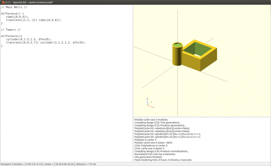
Add the following below the tower cylinder:
cylinder(6,1.5,1.5, $fn=35);
translate([0,0,5.7]) cylinder(2,1.2,1.2, $fn=35);
This creates a new cylinder and translates it to the top of the main cylinder.

Adding a difference function around these two lines will create the hole and our parapet.
difference() {
cylinder(6,1.5,1.5, $fn=35);
translate([0,0,5.7]) cylinder(2,1.2,1.2, $fn=35);
}
Adding more Towers
Now that we have one tower we need to add three more on each corner. We could simply duplicate the script and translate each but there is a slightly better approach.
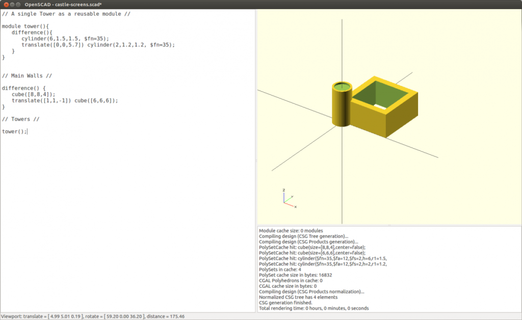
We are going to create a module for the tower that can be reused multiple times. This means we can make a change to the tower in one place and it will change all versions of that tower.
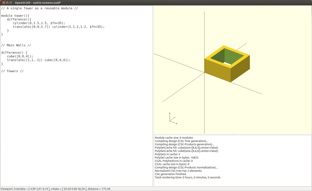
To do this move all of the cylinder script to the top of the script area and wrap it in the following module script:
module tower() {
difference() {
cylinder(6,1.5,1.5, $fn=35);
translate([0,0,5.7]) cylinder(2,1.2,1.2, $fn=35);
}
}
Notes:
module tower(): This turns everything within the curly brackets into a reusable module called tower. You can create modules for anything that is reusable within your model.
Compile and you will notice the tower has disappeared. This is because the module itself does not get rendered.
To make the tower appear again we can call that module by adding the following line to the bottom of your script:
tower();
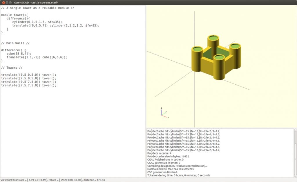
You can now translate this particular tower in the normal way
translate([0.5,0.5,0]) tower();
Do this for each tower and change the translate for each to position it correctly and you should end up with something like this in your script:
// Towers //
translate([0.5,0.5,0]) tower();
translate([7.5,0.5,0]) tower();
translate([0.5,7.5,0]) tower();
translate([7.5,7.5,0]) tower();
Compile (F5) and the castle should look like this:
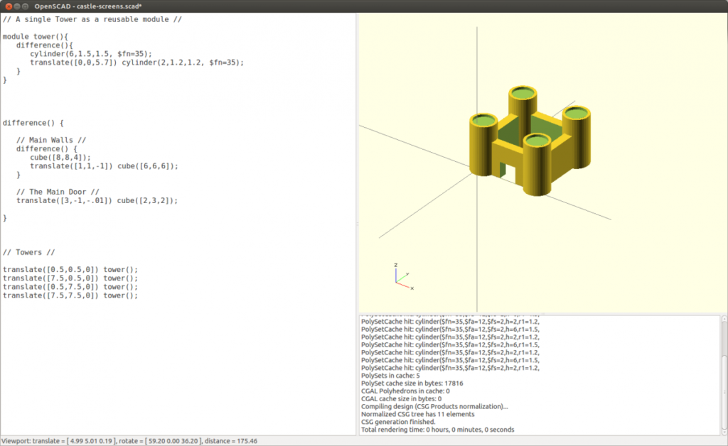
The Door
The door will simply be a cube cut out of the main walls. We will use the difference function and a translated cube to do this.
Directly under the main wall script add the following:
// The Main Door //
translate([3,-1,-.01]) cube([2,3,2]);
and wrap them both in a difference function so the whole Wall and Door script looks like this:
difference() {
// Main Walls //
difference() {
cube([8,8,4]);
translate([1,1,-1]) cube([6,6,6]);
}// The Main Door //
translate([3,-1,-.01]) cube([2,3,2]);
}
Note:
We have wrapped a difference function with another difference function. You can do this with other functions as well and can do this as many times as required as long as you remember what they are all for (comments and tabbing the lines really helps).
Compile (F5) and you should see a small castle with towers and a hole in one wall.
Exporting for 3D Printing
The final file format will be STL as this is a common format for use in 3D printing.
In the Design menu select Compile and Render (F6) to get the final rendered version. It may take a little longer than the standard Compile used previously. Once it has completed select Export STL from the Design menu and save this new file as castle.stl. That is the last stage for OpenSCAD and you should now have a STL file we can bring into a 3D printing tool.
3D Printing
There are a few different tools for sending files to a 3D printer. Common options include:
ReplicatorG: http://replicat.org/
Makerware: http://www.makerbot.com/makerware/
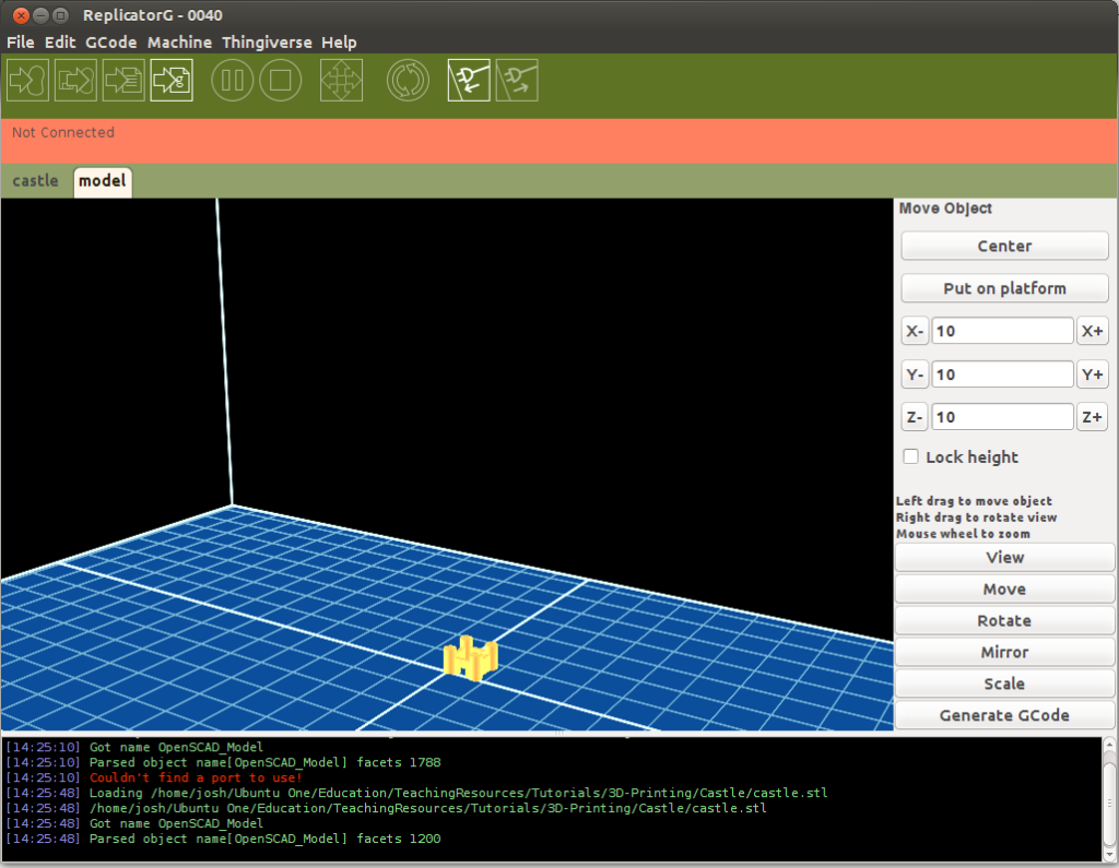
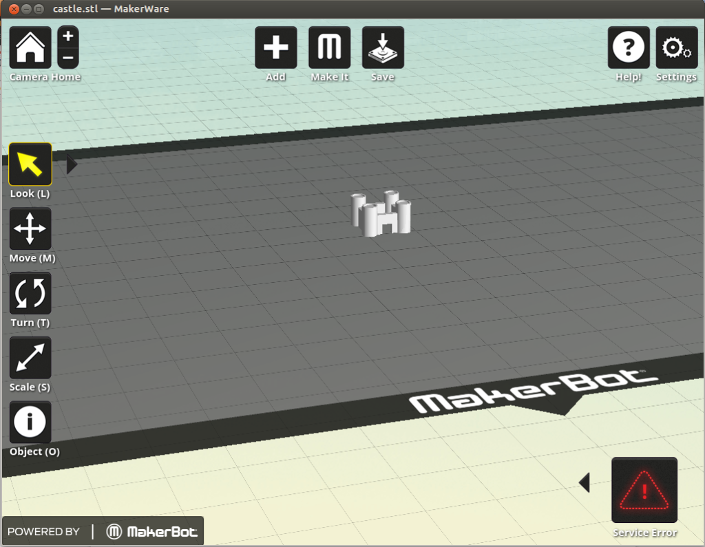
The final print
The final print from a Makerbot Replicator2 looks like this: